
Subsea Pipeline Inspection Services in Egypt
Diver-led condition survey of subsea pipelines: spans, exposure, coating, CP potentials and anode condition, reported against position
Suez-based team 18+ years' experience Response within 24 hours
Pipelines give trouble slowly, and mostly out of sight. A span grows several metres longer between surveys, a section works its way out of its trench, an anode goes from half consumed to detached, an anchor nobody reported leaves a gouge. Almancy carries out diver-led external condition surveys of subsea pipelines, risers, tie-ins and terminal intake lines in Egyptian waters, recording every finding against position so the result goes into the operator's integrity file rather than a folder of unlabelled photographs.
The survey is one step in an integrity management cycle
DNV's recommended practice for integrity management of submarine pipeline systems, RP-F116, sets out the loop an operator is expected to run: risk assessment and inspection planning, then the inspection, monitoring and testing itself, then integrity assessment against those results and the historical record, then any mitigation or repair that follows. An external diver survey lives in the second step, and almost all of its value is decided by how well it feeds the third.
That changes what a useful survey looks like. Intervals are set on risk rather than on the calendar, with probability and consequence of failure judged per section, so two stretches of the same line can sit on different cycles. It also explains why cosmetic findings matter: a gouge from a trawl board or a dragging anchor can act later as an initiation site for fatigue crack growth, so an unremarkable scar gets measured and photographed.
Regulators expect a record. The United States offshore rules, to take one published example, set inspection intervals for indications of leakage, an annual pipe-to-electrolyte potential measurement where cathodic protection design life is under 20 years, and a two-year retention period. We hold no approval under that regime, but reports are written to that shape.
Position referencing: what makes a pipeline finding usable
A finding without a position is an anecdote. Every observation is tied to a chainage or KP value measured from an agreed fixed datum, usually a riser base, a tie-in flange, a valve assembly or the shore crossing, and carries the clock position around the circumference, the depth, and a time stamp that indexes back into the video.
The reason is comparison. A span that measured 8 metres last year and 14 metres now is a different asset from a span that has not moved, and neither statement can be made unless both surveys point at the same piece of steel. The same goes for anode depletion, coating breaks, newly exposed sections and lateral movement off the as-laid route. Change is the actual product; one survey alone only sets a baseline.
The method is fixed in writing before anyone gets wet. On short and mid-length lines, divers measure along the pipe from fixed reference points, count concrete joints, and log markers and crossings as secondary datums. A long route needing survey-grade acoustic positioning is partner scope, priced as such at quotation stage.
What gets recorded along the line
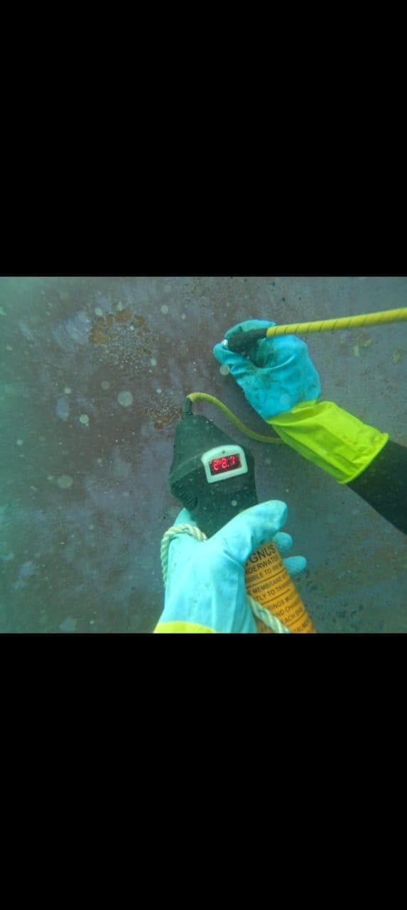
On cathodic protection the reference numbers come from DNV-RP-B401: minus 0.80 volts against a silver/silver chloride seawater electrode is the accepted protective potential for carbon and low-alloy steel, minus 0.80 to minus 1.10 volts is the working range for aluminium or zinc anode systems, and potentials more negative than about minus 1.15 volts count as over-protection. Readings are taken by contact stab, with anodes cleared of debris and growth first, because a reading through a mat of fouling is not a reading. Anode depletion has the same limit: an anode buried in sediment, under rock or hidden by growth cannot be dimensioned reliably, so we report it as not assessed instead of guessing.
Risers earn separate attention at the splash zone. That band is cyclically wetted, wave-loaded and sitting in oxygenated seawater, cathodic protection does not function above the waterline, and corrosion rates reported under riser clamps and hangers reach the order of a millimetre per year. It is also the hardest band to inspect, since thickness measurement there needs marine growth and coating taken off first.
- As-laid position, route deviation and lateral movement against the alignment sheet
- Burial depth and cover, with buried-to-exposed transitions logged as positions, not impressions
- Free span location, span length, pipe-to-seabed gap and shoulder condition
- Scour, seabed mobility, sand waves and ripple fields in the corridor
- Supports and stabilisation: grout bags, concrete mattresses and rock placement, their condition and displacement
- Concrete weight coating cracking, spalling and loss, and field joints, the discontinuity in the weight coat and a known strain concentration
- External coating damage and disbondment, under which a large share of external corrosion is found because the disbonded film shields the cathodic protection
- Cathodic protection potentials along the line, anode condition and estimated depletion
- Marine growth type, coverage and thickness
- Third-party damage: anchor drag scars, trawl marks, dropped objects and debris on the line
- Crossings, clamps, spool pieces, tie-ins and flanges
- Riser and splash-zone condition, including steel under hangers and clamps
- Leak indications, and ultrasonic thickness points where the line can be cleaned to bare metal
Free spans, scour and the decision to intervene
A free span is a length of pipeline with nothing under it, usually because current has scoured the seabed away or because the line was laid over uneven ground. Two failure routes follow: over-stress from self weight, contents and static current load, and fatigue from vortex-induced vibration, both in line with the flow and across it, under combined wave and current loading.
There is no single allowable span length. DNV-RP-F105 makes it a function of the pipe (diameter, wall thickness, coating, the fatigue curve applied), the environment (current velocity, wave-induced velocity and period), the soil stiffness at the shoulders and the gap to the seabed. Marine growth counts too, changing the effective diameter and the vibrating mass. Shallow water does not simplify it: waves in depths under roughly 150 metres are a major source of dynamic load, and the Gulf of Suez sits well inside that band, so a line in 40 metres can behave more actively than its depth suggests.
The survey's job is not to decide a span is acceptable. It is to hand the engineer the inputs: length, gap, shoulder conditions, seabed type, adjacent spans, and how each has changed. Where rectification is called for, the shallow-water answers are usually grout or sand bags placed under the span to shorten it, mattresses, or rock placement on larger scopes. That is construction work, and it goes to our marine construction team on its own scope.
The capability envelope, stated plainly
Our divers work to 50 metres on surface-supplied equipment, and in Egypt that boundary is less restrictive than it sounds. The Gulf of Suez is a shallow basin with a maximum depth around 70 metres and an average nearer 40, while terminal intake and outfall lines and canal-corridor crossings sit shallower still, so a large share of the genuinely diver-accessible pipeline work in the country falls inside the envelope. Deeper work, or a long route needing continuous geophysical coverage, is arranged through specialist partners. Almancy does not own or operate ROVs, AUVs, side-scan sonar, multibeam or sub-bottom profiling equipment, and will not put them on a proposal as though it did.
The second boundary is internal versus external. In-line inspection, commonly called intelligent pigging, runs inside the pipe with a magnetic flux or ultrasonic tool and measures wall loss around the full circumference over the whole length; it needs launch and receive facilities and a geometry the tool can pass, and industry commentary puts the non-piggable share of subsea lines at around 80 per cent. A diver survey is the opposite instrument. It sees the outside, the seabed, the supports and the protection system, and nothing of internal corrosion. We do not offer in-line inspection.
Ultrasonic thickness measurement carries its own limit. The probe needs bare, clean metal, so every reading costs local cleaning and, on a coated line, local coating removal. Intact concrete weight coating rules the method out altogether. Diver ultrasonic work on a pipeline is therefore a defined set of readings at agreed positions, never a continuous wall-thickness profile; for the technique itself, our guide to underwater NDT methods and the broader underwater inspection page cover it.
Where the line forms part of an operating terminal, port services covers the berth and intake work around it.
How the work is carried out
- 1
Data handover and scope agreement
We ask for as-laid drawings and alignment sheets, the previous survey report, the CP design and anode layout, and the existing anomaly list. Without the previous report the survey can only produce a baseline, which is worth saying before the quote is signed.
- 2
Method statement and referencing plan
The datum, the chainage method, the measurement points, the extent of cleaning and the interface with any isolation or permit regime are agreed in writing before mobilisation.
- 3
Baseline pass along the line
A general visual run with continuous video to establish overall condition, log burial and exposure transitions, locate spans, and flag every position that needs a closer look.
- 4
Close examination and measurement
Divers return to the flagged positions to clean where required, dimension damage and spans, take CP potentials by contact stab, measure anodes, and take UT readings at the agreed points.
- 5
Anomaly register and comparison
Findings are written up against position, with dimensions, photographs and video references, and set beside the previous survey so change is visible rather than implied.
- 6
Recommendations and handover
We separate what needs intervention now, what needs an engineering assessment such as a span check, and what simply needs re-inspecting at the next interval.
What you receive
- Anomaly register listing each finding with chainage or KP, clock position, depth, dimensions and a photo or video reference
- Span table giving location, span length, pipe-to-seabed gap, shoulder conditions and seabed type
- Cathodic protection data set: potentials at each stab point, the reference electrode used, anode dimensions and estimated depletion, with unmeasurable anodes marked as such
- Ultrasonic thickness record with point identifiers, surface preparation confirmed, readings and the nominal thickness they are compared against
- Time-stamped HD video and stills indexed to position so any finding can be re-opened later
- Marked-up alignment sheet or route sketch showing exposure, spans, supports, crossings and damage
- Findings report with comparison to the previous survey and a separated list of intervention, assessment and re-inspection items
What we need to quote
A pipeline survey is quoted from the line, the route and the reporting standard, not from length alone. The more of the following you can send, the closer the first quote will be to the final invoice.
- Line data: diameter, wall thickness, product, external coating type, and whether the line carries a concrete weight coat
- Route length to be surveyed, the start and end reference points, and the water depth range along it
- Previous survey reports, as-laid drawings or alignment sheets and the current anomaly list
- Cathodic protection system type, anode layout, design life and the date of the last potential survey
- Whether ultrasonic thickness readings are required, how many points, and where cleaning is acceptable on a coated line
- Known or suspected spans, exposed sections, crossings, dropped objects or anchor damage
- Whether the line stays live during the work, and any isolation, permit or terminal-interface requirements
- The reporting format your integrity management system expects, including any anomaly classification scheme you already use
Related Services
Pipeline Inspection: Frequently Asked Questions
Questions we are asked most often about pipeline inspection.
How often should a subsea pipeline be inspected externally?
What does an exposed or spanning section actually mean for me?
Can you measure wall thickness on a coated or concrete-weighted pipeline?
Do you carry out intelligent pigging or in-line inspection?
How deep can you inspect, and do you use ROVs?
Can divers find a leak on a pipeline?
Start Your Project
Scope a pipeline survey against your integrity plan
The line data, the route length and your last survey report are what a real scope is built from. Without the previous report you are buying a baseline rather than a comparison, and it is better to know that before the quote is signed. A suspected leak, a newly exposed section or a reported anchor strike goes to the 24/7 line on +20 109 528 3400, with teams mobilising from Suez.